A vibration shaker works by converting electrical energy into controlled mechanical motion, using either an electrodynamic coil-and-magnet system or a mechanical exciter to push a moving table or armature back and forth at precise frequencies and amplitudes. This motion is transferred to a mounted test article to simulate real-world vibration, shock, or acoustic environments. The core principle is electromagnetic force: an alternating current passed through a coil inside a magnetic field generates a reciprocating force proportional to the current, which drives the shaker table.
Understanding this mechanism matters for anyone specifying test equipment, because the shaker type, exciter design, and control system together determine what frequencies, forces, and payloads can be tested accurately.
The Core Working Principle of a Vibration Shaker
Most modern vibration shakers are electrodynamic. A stationary field coil or permanent magnet assembly creates a strong, fixed magnetic field inside an air gap. A moving coil, called the drive coil, sits inside this gap and is rigidly attached to the shaker's moving armature and table. When an amplified alternating current from a power amplifier flows through the drive coil, it interacts with the magnetic field to produce a force according to the Lorentz force law: F = B × I × L, where B is magnetic flux density, I is current, and L is the length of wire in the field.
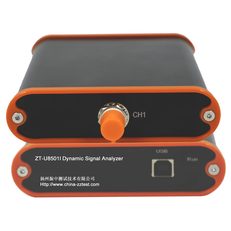
Because the force is directly proportional to current, a controller can shape the input waveform to produce sine sweeps, random vibration, shock pulses, or complex mission profiles. A closed-loop control system with an accelerometer feedback sensor continuously compares the actual table motion to the target profile and adjusts the signal in real time, often correcting deviations within milliseconds.
Key Components That Make It Work
- Field coil or permanent magnet assembly — generates the static magnetic field
- Drive coil (voice coil) — carries the alternating current and generates force
- Armature and flexures — support the moving mass while allowing linear travel
- Power amplifier — boosts the control signal to drive current levels
- Cooling system — removes heat generated by continuous current flow, usually via blower or water cooling
Modal Shaker Exciter: Purpose and Design
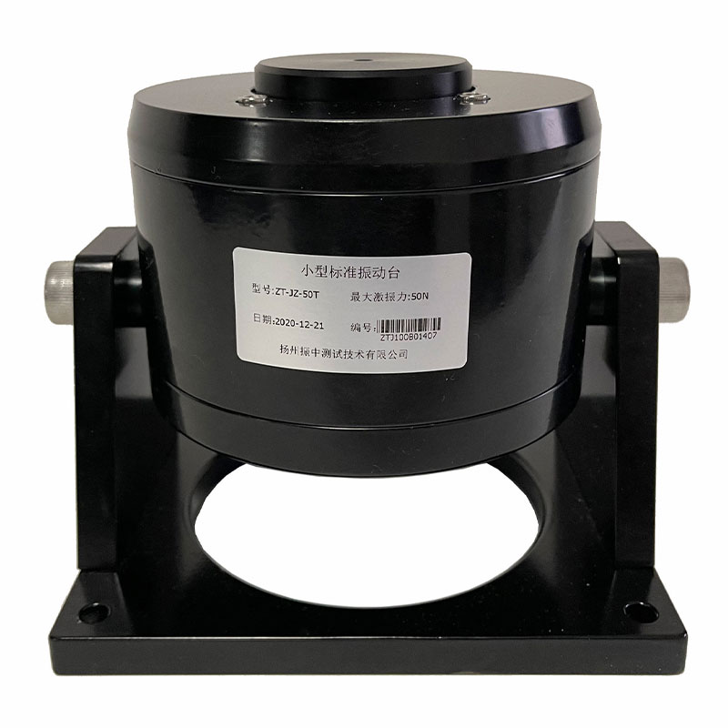
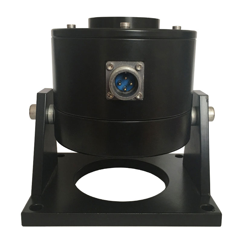
A modal shaker exciter is a lightweight, compact electrodynamic exciter designed specifically for modal analysis and structural testing rather than large-scale environmental qualification. Its job is to inject a known, controllable force into a structure so engineers can measure the structure's resonant frequencies, mode shapes, and damping characteristics.
Unlike standard shakers, modal exciters are typically rated for lower force output, often between 5 N and 500 N, and are built with minimal moving mass so they do not distort the test structure's natural dynamic behavior. They are commonly suspended by soft bungee cords or mounted on a stinger rod to isolate the exciter's own mass and stiffness from the structure under test.
Typical Applications
- Experimental modal analysis of aircraft components, automotive bodies, and civil structures
- Frequency response function (FRF) measurement for finite element model validation
- Structural health monitoring and fatigue root-cause investigation
- Small-scale component resonance search prior to full qualification testing
Stinger Connection Matters
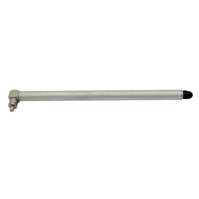
The exciter connects to the test structure through a thin stinger rod, usually a slender steel or nylon rod, which transmits axial force while preventing the exciter from adding unwanted bending stiffness or mass loading to the structure. A poorly selected stinger can introduce measurement errors of several percent in identified natural frequencies, so stinger length and diameter are chosen based on the expected force and frequency range.
Standard Vibration Shaker: Structure and Capability
A standard vibration shaker is a full-scale production or laboratory system built for environmental and reliability testing under recognized standards such as MIL-STD-810, IEC 60068-2, and ISO 16750. These systems range from small benchtop units delivering under 100 N of force to large systems exceeding 100 kN of sine force output, capable of testing entire subassemblies or full products.
Standard shakers integrate a rigid armature, a head expander or slip table for larger payloads, and a dedicated control system that runs standardized test profiles, including sine sweep, random vibration, and shock testing, often unattended for hours or days.
Comparing Shaker Types by Application
Comparison of modal exciters and standard vibration shakers by typical use case and output range
| Feature |
Modal Shaker Exciter |
Standard Vibration Shaker |
| Force range |
5 N to 500 N |
100 N to 100+ kN |
| Primary use |
Modal analysis, FRF testing |
Environmental and qualification testing |
| Connection method |
Stinger rod, bungee-suspended |
Direct table mount or slip table |
| Test duration |
Minutes per measurement |
Hours to days |
Choosing the Right Shaker for Your Test
Selecting between a modal exciter and a standard shaker depends on what question the test needs to answer. If the goal is to identify a structure's natural frequencies or validate a simulation model, a modal exciter with a force transducer and accelerometer array is the appropriate choice. If the goal is to prove a product survives transportation, operational vibration, or shock events per an industry standard, a standard shaker with sufficient force rating and frequency range is required.
A practical rule of thumb: the shaker's usable frequency range should extend at least 20% beyond the highest frequency of interest, and the force rating should account for the combined weight of the test article and any fixture, since fixture mass reduces the maximum achievable acceleration.
Quick Selection Checklist
- Confirm required frequency range covers the structure's expected resonances
- Calculate total moving mass including fixture and payload
- Match force rating to peak acceleration and mass requirements
- Verify whether the test needs sine, random, or shock capability
- Check cooling and duty cycle limits for long-duration tests

 English



















 Address : No. 85, Hetao West Road, Hanjiang District, Yangzhou City, Jiangsu Province, China
  Phone: +86-0514-85764839
  Tel: +86-0514-85764839
  Email: sales@china-zztest.com