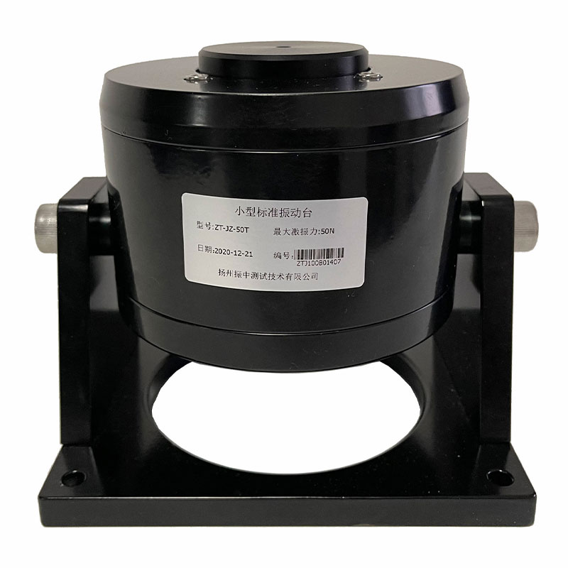
A modal shaker exciter is an electromechanical device that converts an electrical drive signal into a controlled mechanical force, applied directly to a test structure so engineers can measure its natural frequencies, mode shapes, and damping. Instead of relying on an impact hammer's single transient hit, the exciter sustains a repeatable, tunable force over a defined frequency band, which is why it remains the preferred excitation method for structures that need sine sweeps, random vibration, or long-duration fatigue input.
How a Modal Shaker Exciter Works
At its core, a modal shaker exciter operates on the same principle as a loudspeaker driver, scaled up for structural loads. A power amplifier feeds an alternating current into a coil suspended inside a magnetic field. The interaction between the current-carrying coil and the magnetic field generates a force along the shaker's drive axis, following the Lorentz force relationship: force is proportional to the magnetic flux density, the coil length in the field, and the current supplied. Because current can be controlled with high precision, the resulting force can be shaped into a pure sine tone, a swept sine, random broadband noise, or a shaped transient — whichever excitation profile the test plan calls for.
The armature, which carries the coil and connects to the test structure through a drive rod, is supported by a flexible suspension system. This suspension keeps the armature centered and prevents it from moving in any direction other than the intended drive axis, which directly affects how "clean" the force input is. Any lateral or rocking motion introduces cross-axis force components that corrupt the frequency response function being measured, so suspension quality is one of the most understated performance factors in exciter design.
Core Components That Determine Performance
Every modal shaker exciter, regardless of size, is built around the same functional blocks. Understanding how they connect helps when troubleshooting inconsistent test data or specifying a system for a new application.
Signal & Power Chain
Signal Generator
Power Amplifier
Shaker Body (Coil, Armature, Suspension)
Drive Rod / Stinger
Cooling System
Fig. 1 — Functional chain of a modal shaker exciter, from signal generation to mechanical output at the test article.
The signal generator or controller produces the reference waveform and, in closed-loop systems, compares a feedback signal (typically from an accelerometer or force transducer mounted at the drive point) against the target profile, adjusting the drive signal in real time to maintain accuracy. The power amplifier steps up the current to the level the coil requires — for larger shakers this can mean hundreds of amperes at low voltage. The cooling system, whether forced-air or liquid, prevents the coil from overheating during sustained high-force or high-frequency operation; thermal limits are frequently the reason a shaker cannot sustain its rated peak force continuously.
Comparing Excitation Technologies
Three excitation technologies dominate structural testing, and each trades off force capacity, frequency range, and displacement differently.
| Technology |
Typical Frequency Range |
Typical Peak Force |
Best Suited For |
| Electrodynamic |
DC to 10,000 Hz |
20 N to 90,000 N |
General modal testing, sine sweeps, random vibration |
| Piezoelectric |
Up to 20,000 Hz |
50 N to 3,000 N |
High-frequency, small-displacement excitation |
| Hydraulic |
DC to 500 Hz |
5,000 N to over 500,000 N |
Low-frequency, high-force fatigue and durability testing |
Electrodynamic units remain the most common choice for modal analysis because they combine a wide frequency range with linear, predictable force output and relatively simple maintenance. Piezoelectric exciters trade force capacity for extremely high bandwidth, making them useful for small, stiff components where resonances occur well above 5,000 Hz. Hydraulic exciters sacrifice frequency range entirely in exchange for force levels that electrodynamic and piezoelectric systems cannot approach, which is why they dominate structural fatigue and durability rigs rather than modal identification work.
Key Specifications That Affect Test Quality
Selecting or evaluating a shaker exciter comes down to matching four specifications to the test object: peak force, usable frequency range, maximum stroke, and armature moving mass. Undersizing any one of these introduces measurable error into the extracted mode shapes.
450 N
Small bench-top
shaker
2,700N
Mid-range
lab shaker
18,000N
Large structural
test shaker
89,000 N
Heavy component
test shaker
Fig. 2 — Representative peak sine force ranges across common electrodynamic shaker size classes.
Force sizing needs to account for more than the structure's static mass. At resonance, the effective dynamic force required to drive a lightly damped structure to a measurable response can be a small fraction of what would be needed to move an equivalent static mass, because the structure itself amplifies the input near its natural frequencies. However, as frequency drops toward the low end of the sweep, the force needed to achieve the same displacement amplitude rises sharply — displacement, velocity, and acceleration are related by factors of frequency, so a shaker that looks adequately sized at mid-band can run out of stroke or force at 5 Hz. A practical rule used by test engineers is to size the shaker for at least 20 percent headroom above the calculated worst-case force requirement across the full frequency range, not just at the expected resonance.
Mounting and Coupling Methods
How the exciter connects to the structure has as much influence on data quality as the shaker's own specifications. Three coupling approaches are used in practice:
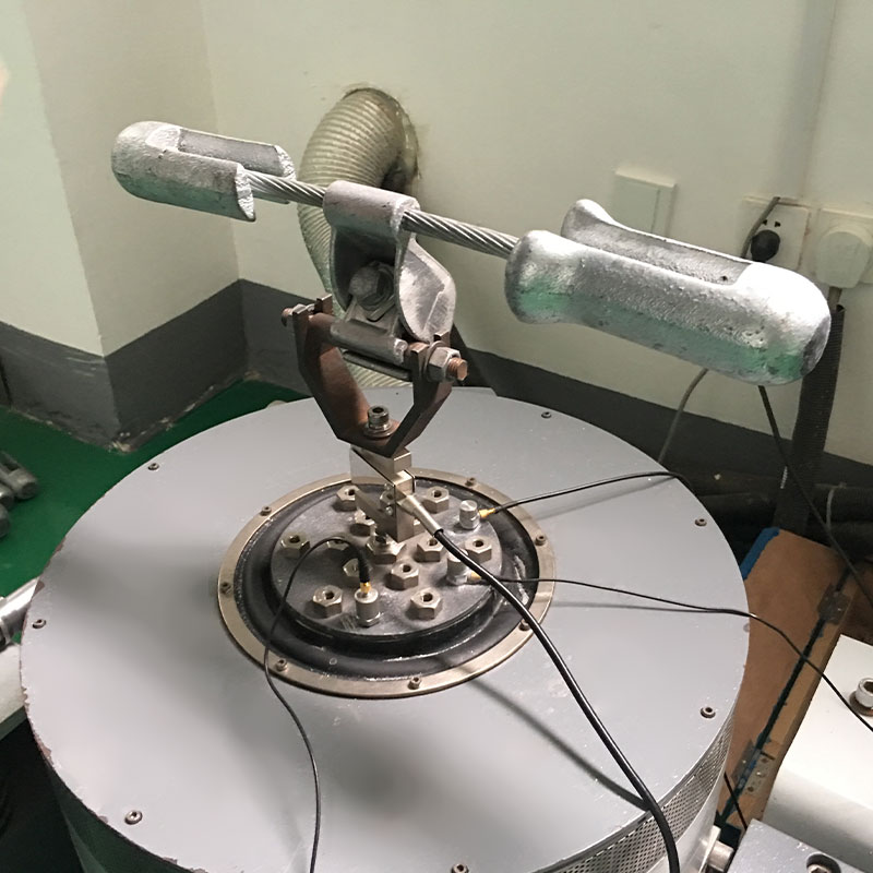
Stinger rod connection — a thin, axially stiff but laterally flexible rod links the armature to the structure. This is the standard method for modal testing because the rod transmits force along the drive axis while its flexibility in bending isolates the structure from unwanted lateral loads imposed by the shaker's own suspension. A stinger that is too short or too stiff in bending reintroduces cross-axis force; one that is too long or thin can itself resonate within the test bandwidth and distort the measured force.
Direct attachment — used when the exciter is small relative to the structure or when very high-frequency work makes stinger compliance unacceptable; requires careful alignment since any misalignment couples directly into the structure.
Reaction mass or free-free suspension — for lightweight structures, the shaker itself needs a stable reaction point, often achieved by mounting the test article on soft bungee cords to approximate a free-free boundary condition, while the shaker is grounded to an independent, vibration-isolated base so its own motion does not couple back into the measurement.
Typical Applications Across Industries
Modal shaker exciters are used wherever engineers need to characterize how a structure responds dynamically before it enters service or after a design change.
- Aerospace structures: wing and fuselage panel modal surveys, satellite component qualification, and ground vibration testing on full aircraft.
- Automotive engineering: body-in-white stiffness verification, powertrain mount tuning, and NVH (noise, vibration, harshness) troubleshooting.
- Civil and structural engineering: bridge and building modal identification for seismic assessment and structural health monitoring.
- Electronics and consumer products: printed circuit board and enclosure resonance testing to prevent fatigue failure from operational vibration.
- Rotating machinery: bearing housing and turbine blade modal characterization to avoid resonance overlap with operating speeds.
Across these fields, the underlying goal is consistent: identify resonant frequencies early enough that a design change is still cheap, rather than discovering a resonance problem after a prototype fails in service.
Signal Chain Integration With Data Acquisition
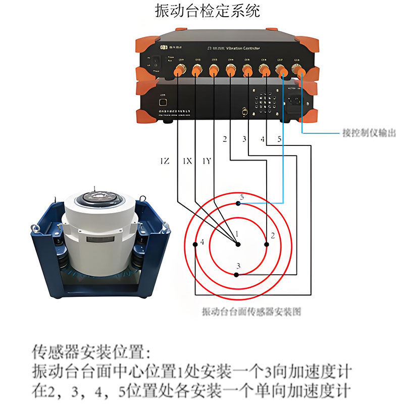
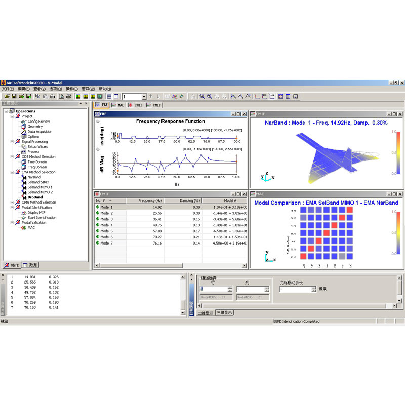
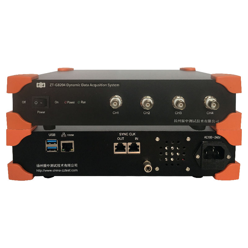
A shaker exciter only produces useful test data when it is properly integrated with sensors and acquisition hardware. A typical setup places a force transducer between the stinger and the structure to measure the actual input force, while one or more accelerometers capture the structural response at multiple points. Both signals feed into a data acquisition system that computes the frequency response function — the ratio of response to input force across frequency — from which natural frequencies, mode shapes, and modal damping ratios are extracted using curve-fitting algorithms.
Closed-loop control is what separates a basic shaker system from a precision one. Rather than driving the shaker with a fixed voltage signal, the controller monitors the actual force or acceleration achieved and continuously corrects the drive signal so the input tracks the intended profile even as the structure's dynamic impedance changes across the sweep. Without this feedback loop, resonances in the test structure can cause uncontrolled force spikes or drops exactly where accurate data matters most.
Common Testing Errors and How to Avoid Them
Several recurring mistakes account for the majority of poor-quality modal test data:
Mass loading — mounting a heavy accelerometer or force transducer on a lightweight structure shifts its natural frequencies downward. Using sensors with a mass under roughly 1 percent of the local structural mass at the mounting point keeps this error negligible.
Stinger resonance — a stinger rod that resonates within the test frequency range introduces a false peak in the measured force. Keeping the stinger short and verifying its first bending mode falls well above the test bandwidth avoids this.
Inadequate boundary conditions — a free-free suspension that is not soft enough relative to the structure's first flexible mode contaminates low-frequency mode shapes with rigid-body motion. A common guideline is keeping suspension rigid-body frequencies below one-tenth of the structure's first elastic mode.
Overdriving at resonance — because lightly damped structures amplify response sharply near resonance, a constant-force sweep can drive displacement past linear limits, introducing nonlinear distortion into the frequency response function. Controlled-response testing, where the controller reduces force as resonance is approached, avoids this.
Poor grounding of the shaker body — if the shaker's own body is not adequately isolated or grounded, reaction forces couple back into the measurement setup, degrading repeatability between test runs.
Maintenance Practices That Extend Service Life
Electrodynamic exciters are precision instruments, and their long-term accuracy depends on routine upkeep. Coil temperature should be monitored during extended test campaigns, since repeated thermal cycling accelerates insulation breakdown. Suspension components — typically flexures or roller bearings — wear gradually and should be inspected for play or asymmetric stiffness, since degraded suspension is a common source of unexplained cross-axis force appearing months after a system was last calibrated. Stingers are consumable items and should be replaced whenever bent or fatigued rather than reused indefinitely. Amplifier and cooling system filters also need periodic cleaning, particularly in dusty industrial test environments, to prevent airflow restriction that leads to thermal shutdowns mid-test.
What is the main difference between a modal shaker exciter and an impact hammer?
A shaker exciter applies a continuous, controllable force over a chosen frequency range or time period, while an impact hammer delivers a single transient impulse. Shakers give better control over force amplitude and frequency content, which matters for nonlinear structures or when high signal-to-noise ratio is needed at specific frequencies.
How do I choose the right force rating for a modal shaker exciter?
Calculate the dynamic force needed across the full frequency range of interest, including the low-frequency end where stroke and force demands are typically highest, then add roughly 20 percent headroom. Undersized shakers cannot reach target amplitudes at the lower end of a sweep even if they perform well near resonance.
Can a modal shaker exciter damage the test structure?
Yes, if force levels are not controlled near resonance. Because lightly damped structures amplify response sharply at natural frequencies, an uncontrolled constant-force sweep can drive the structure into nonlinear or even damaging displacement levels. Closed-loop control that limits response amplitude near resonance prevents this.
Why does stinger rod selection matter so much in modal testing?
The stinger transmits axial force while isolating the structure from the shaker's own lateral suspension motion. A stinger that is too stiff in bending reintroduces cross-axis force, while one that is too long or thin can resonate within the test band, distorting the measured force signal.
What frequency range should I expect from an electrodynamic shaker exciter?
Most electrodynamic shakers used in modal testing cover from near DC up to somewhere between 5,000 and 10,000 Hz, depending on size and armature design. Larger, high-force units tend to have a narrower upper frequency limit due to increased armature mass, while smaller units reach higher frequencies but with lower force capacity.
References
- Ewins, D.J., "Modal Testing: Theory, Practice and Application," Research Studies Press, 2nd Edition.
- ISO 7626: Mechanical vibration and shock — Experimental determination of mechanical mobility.
- ASTM E756: Standard Test Method for Measuring Vibration-Damping Properties of Materials.
- Rao, S.S., "Mechanical Vibrations," Pearson Education.
- McConnell, K.G., and Varoto, P.S., "Vibration Testing: Theory and Practice," Wiley.

 English



















 Address : No. 85, Hetao West Road, Hanjiang District, Yangzhou City, Jiangsu Province, China
  Phone: +86-0514-85764839
  Tel: +86-0514-85764839
  Email: sales@china-zztest.com