A commissioning engineer walks onto a turbine deck with eight accelerometers, a laptop, and no way to run cables from the bearing housings to a control room without crossing a walkway. This is the moment wireless data acquisition stops being a convenience and becomes the only practical option. But the phrase "wireless data acquisition" describes two very different system architectures, and choosing the wrong one for vibration or noise testing can cost you phase accuracy, channel count, and weeks of troubleshooting. The short version: for most mechanical measurements, wireless belongs between the acquisition front-end and the host computer, not between the sensor and the digitizer.
What "Wireless Data Acquisition" Actually Covers
When vendors use the term, they generally mean one of two layouts.
Autonomous wireless sensor nodes
Each node is a self-contained measurement point: a sensor input, a low-power analog-to-digital converter, a battery, and a radio. These nodes communicate directly with a gateway that forwards data to software. They are a good fit for widely distributed points where sample rates stay low and you do not need channel-to-channel phase matching between separate nodes.
Networked acquisition front-end with wireless transport
The second architecture keeps the digitizer close to the sensors but replaces the final cable run with a radio link. A multi-channel dynamic signal analyzer sits at the measurement location, and that analyzer connects to the host PC over Wi-Fi, a cellular modem, or a private radio bridge. The sensors are still cabled, but the long, fragile returns to the control room are gone.
This distinction matters because it decides how much of each measurement attribute you keep. A battery-powered node that samples at a few kilo-samples per second is useful for routine condition screening. It is not the tool for a 16-channel modal test that needs a 20 kHz analysis bandwidth. Before evaluating any supplier, identify which architecture matches your test object and signal type.
Five Things to Verify Before You Choose
Wireless implementations fail in predictable ways. Check these five points against any quoted system before you commit.
- Channel synchronization. Each radio-connected node carries its own clock. If nodes do not share a time base, relative phase between channels drifts. Verify the synchronization mechanism: some systems time-stamp every sample and correct drift in software; others lock to a radio beacon. Ask for a concrete phase error figure over a defined measurement duration.
- Sampling rate versus bandwidth. A single Wi-Fi link is shared throughput. Eight nodes at 51.2 kS/s each on one access point will not deliver continuous data; they will buffer, drop frames, or down-sample. Confirm the continuous per-channel rate with your node count and expected duty cycle.
- Sensor compatibility. Vibration transducers are far from uniform. Charge accelerometers need a charge amplifier; IEPE accelerometers need constant-current excitation; strain bridges need bridge completion and a precision voltage source. If the wireless node cannot supply excitation or terminate the sensor correctly, you have not removed the conditioning box from the chain.
- Power logistics. Batteries are the usual cause of silent data loss. For a monitoring application that must run for months, a "wireless" node with a three-week battery life is still a cable to a solar panel or an AC adapter. The honest question is whether you are eliminating the data cable or simply replacing it with a shorter power cable.
- Radio environment. Sheet-metal enclosures, concrete decks, motor drives, and other plant structures attenuate 2.4 GHz and 5 GHz band signals. Plan for antenna placement on the outside of test objects, and check the link budget rather than trusting the claimed open-air range.
The Architecture That Works for Vibration and Noise Testing
For vibration, noise, and modal work, the local-digitizer approach is the one that holds up. The analyzer remains a proper dynamic signal analyzer - with a 24-bit converter, per-channel anti-aliasing filters, IEPE and charge inputs, and controlled channel-to-channel phase matching - and only the backhaul to the host is wireless. Multiple analyzers can be placed at several physical clusters, each handling six, eight, or sixteen channels, while a single PC supervises the test from a trailer or control booth.
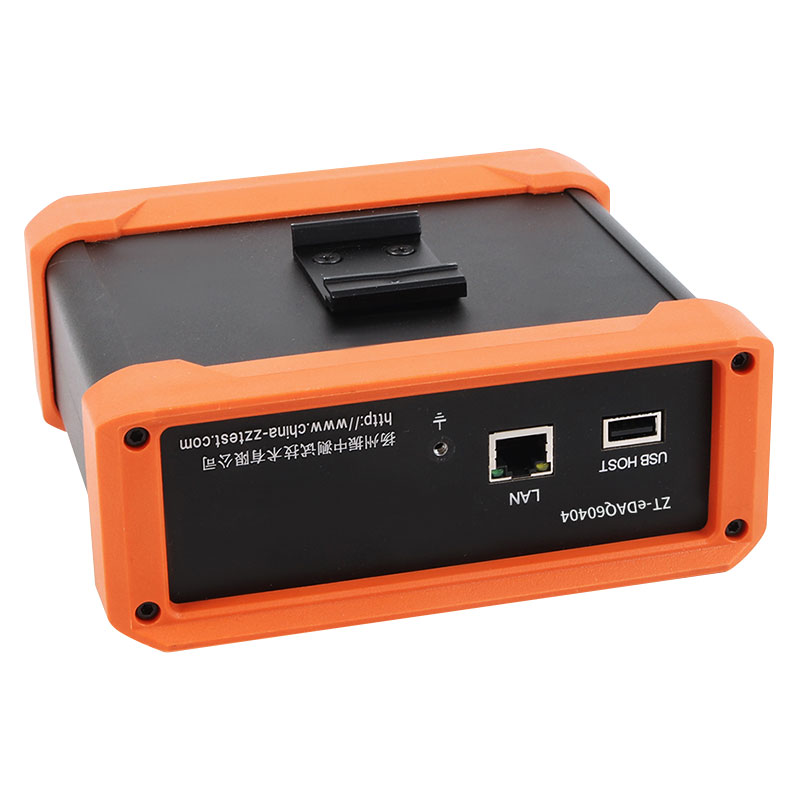
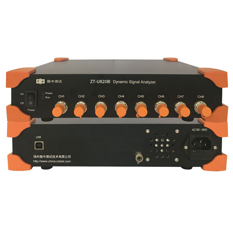
This is where the trade-off between convenience and fidelity finally comes into balance. A networked instrument like the ZTN8208I accepts voltage and IEPE inputs on eight channels and streams continuously over a 100 Mbps Ethernet link, which you can connect to a wireless bridge without any change to the measurement path. If you want to know how a dynamic signal analyzer differs from a traditional data logger, the answer is in the input conditioning and the fixed sampling architecture rather than in the radio.
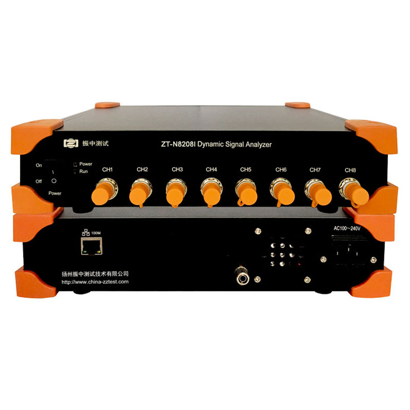 ZT-N8208I Voltage/IEPE Dynamic Signal Analyzer with Ethernet StreamingThis eight-channel analyzer supports voltage and IEPE inputs with a 24-bit architecture, delivering low noise and continuous streaming over 100 Mbps Ethernet. It fits high-fidelity measurement setups where sensor signals must be digitized accurately before wireless transport.View Product →
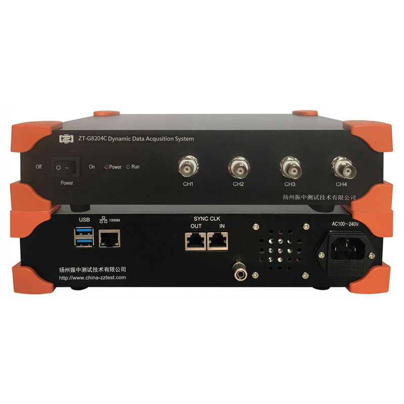
When a test demands lower noise floors and higher data throughput, gigabit network analyzers are the next step. The ZTG8204C, a four-channel low-noise model with the same 24-bit architecture, suits high-accuracy frequency response measurements where the excitation level is small and every microvolt of sensor signal must survive the digitization intact.
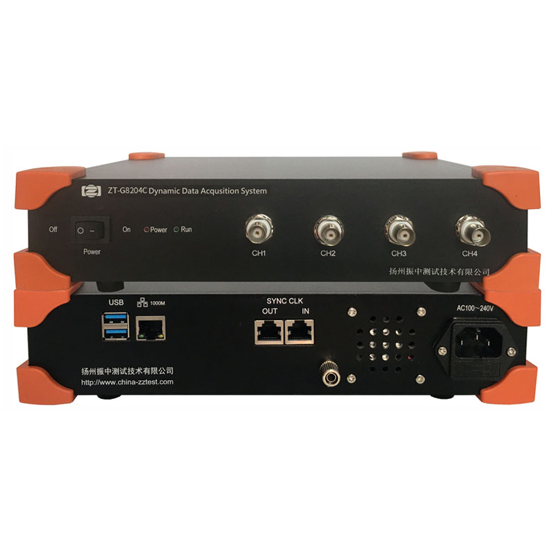 ZT-G8204C Low-Noise Four-Channel Dynamic Signal AnalyzerWith gigabit Ethernet sampling up to 128 kHz per channel and the same 24-bit converter, this low-noise analyzer suits small-excitation frequency response tests where preserving every microvolt of sensor signal is critical.View Product →
Where Wireless Data Acquisition Earns Its Keep
The strongest justification for wireless is not lab convenience; it is access. Three application groups keep coming back.
Rotating machinery and in-plant condition monitoring
Motors, pumps, compressors, and fans sit in locations where running instrumentation cable is expensive, unsafe, or impossible while the machine is operating. A local analyzer connected to the plant network reports overall levels, bearing frequencies, and spectra to a central monitoring screen without anyone climbing the structure.
Civil structures and outdoor testing
Bridge, tower, and pipeline surveys commonly cover long spans with no power on site. Distributed analyzers with local DC supplies and wireless backhaul allow the test crew to capture traffic-induced vibration without stringing cable along the span. A compact four-channel unit such as the ZTN8204C keeps the per-point cost low while retaining voltage and IEPE inputs, which is usually enough for this class of work.
Vehicle and transport testing
When the object under test moves, a cable to a stationary computer is either a constraint on motion or a hazard. Wireless transport between the on-board analyzer and the following vehicle or control booth solves this cleanly.
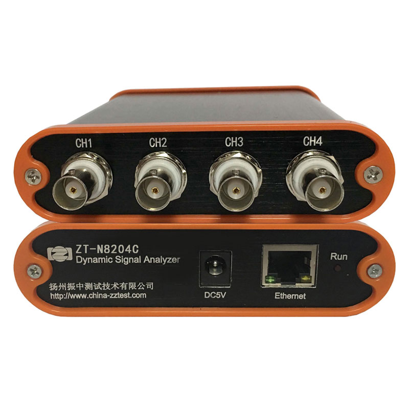 ZT-N8204C Three-in-One Multi-Channel Data Acquisition AnalyzerThis analyzer accepts IEPE, charge, and voltage inputs with built-in gain conditioning, eliminating external adapters. It is well suited for moving or rotating test objects where on-board digitization and wireless data transport replace cable constraints.View Product →
In each case, the shared feature is that the sensors record at a measurement location close to the structure, while only the data transport is wireless. Where simple vibration levels are enough, low-power nodes still have their place; where phase, bandwidth, or dynamic range matters, digitize locally and transmit afterward.
A Practical Checklist for Comparison
When evaluating quotations side by side, a table is more useful than a feature list. The comparison below reflects typical specifications across the three approaches discussed.
Typical characteristics of wireless data acquisition approaches for vibration and noise measurement
| Attribute |
Wireless sensor node |
Local DAQ + wireless backhaul |
Fully wired system |
| Channel-to-channel phase |
Drifts between nodes |
Fixed within one unit |
Fixed within one unit |
| Typical continuous sample rate |
0.2-5 kS/s per node |
Up to 128 kS/s per unit |
Unrestricted |
| IEPE/charge input support |
Often absent |
Standard |
Standard |
| Power requirement |
Battery, periodic exchange |
DC supply at the unit |
From host or mains |
| Best fit |
Wide-area level monitoring |
Modal, noise, machinery tests |
Bench and laboratory work |
Notice what the middle column gives you: the same measurement attributes as a cabled analyzer, minus the long cable run. When the scope grows beyond a single analyzer - excitation, sensors, acquisition, and analysis software in one turnkey package - complete vibration and dynamic testing systems cover that scope as a single engineering effort.
The practical rule for wireless data acquisition is short and unsentimental: make the radio link carry the least sensitive part of the signal chain. Keep sensors connected to a real acquisition front-end, keep that front-end close to the measurement point, and use wireless only for the final connection back to the person who needs the data. When you do that, wireless ceases to be a compromise and becomes a reliable tool for vibration, noise, and modal testing - and the long cable runs stay in the drawer where they belong.

 English



















 Address : No. 85, Hetao West Road, Hanjiang District, Yangzhou City, Jiangsu Province, China
  Phone: +86-0514-85764839
  Tel: +86-0514-85764839
  Email: sales@china-zztest.com