A cable is the least interesting part of a force measurement, right up until it is not. It picks up noise from a drive cabinet two bays away, it fatigues at the connector after a few thousand cycles, it snags on a moving fixture, and it turns a forty-channel bridge test into two days of instrumenting. That is the honest reason wireless force sensors moved from novelty to standard tool in structural, industrial and research testing.
What follows is a practical look at how cable-free force measurement actually works, where it genuinely outperforms a wired chain, where it quietly does not, and which specifications decide whether a number on a screen deserves to be trusted. It is written from the perspective of a team that builds force, vibration and dynamic testing hardware for a living, so the emphasis stays on what survives contact with a real test.
The short version
- A wireless force sensor is a measurement chain, not a single component. The transducer, conditioning, conversion, radio and power all still have to exist somewhere.
- The radio link is rarely the hard part. Clock alignment, offset handling and battery budgeting are.
- Wireless wins on large structures, rotating parts, moving fixtures and distributed load testing. Wired still wins on high channel counts in a quiet lab.
What a Wireless Force Sensor Really Is
Strictly speaking, a wireless force sensor is a force transducer whose output reaches the data acquisition system over a radio link instead of a cable. In practice the phrase covers several different architectures, and the differences matter when you are specifying a test.
Four arrangements show up most often in real projects:
- An integrated wireless force transducer. A strain-gauge load cell or piezoelectric element, its signal conditioning, an analog-to-digital converter, a radio and a battery share one sealed housing. Easiest to deploy, hardest to repair, and usually the most expensive per channel.
- A conventional force sensor with a wireless transmitter node attached. Common in laboratories that already own calibrated transducers and want to keep using them rather than buy new ones.
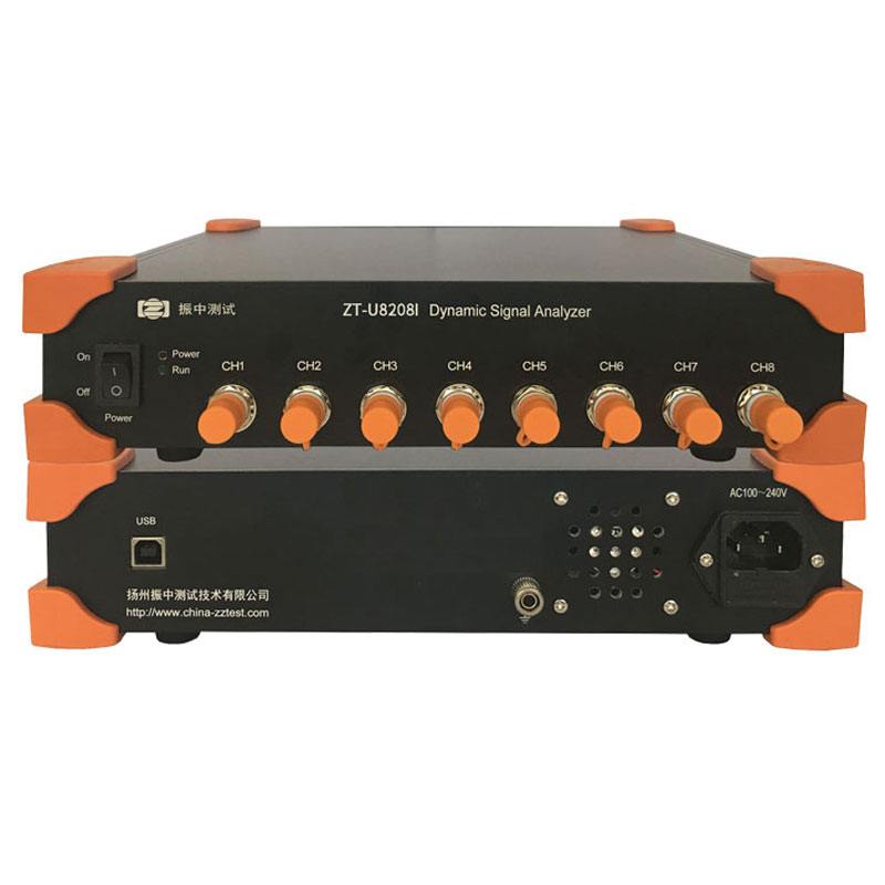
- A multi-channel wireless acquisition node with voltage, IEPE or charge inputs. One node can accept a force sensor, an accelerometer or a microphone, which is what makes mixed force-and-vibration testing on a structure practical.
- Semi-passive and passive designs. RF-powered sensors, piezoresistive arrays and printed flexible elements. Mostly research-stage today, but they point at a future where battery maintenance disappears.
The sensing principle behind the transducer is a separate question that gets decided long before the radio does. Strain-gauge load cells behave well under static and quasi-static load because they need bridge excitation and hold a steady reading. Piezoelectric force sensors are excellent for dynamic events such as impacts and modal excitation, because they generate charge in proportion to the applied force and cannot hold a static value indefinitely. Piezoresistive MEMS elements sit between the two, offering small size and reasonable bandwidth at lower force ranges.
So the first useful question is never "which wireless sensor should I buy". It is "am I measuring static force, dynamic force, or both". Everything else follows from that answer.
The Force Measurement Chain, Link by Link
Cutting the cable does not remove any of the electronics that used to sit behind it. It only moves them. Understanding where they ended up is the fastest way to judge whether a product will hold up in your application.
The sensing element
For dynamic work, a piezoelectric force sensor remains the reference. A modal force hammer is essentially a piezoelectric force sensor with a known mass and a hardened tip, which is why hammer testing and piezoelectric measurement are almost always discussed together. For static and slow-varying loads, bonded foil strain gauges in a full bridge are still the workhorse, provided the temperature is controlled and the bridge excitation is clean. Whatever the element, its calibration is the part that ultimately gives the number meaning, and a wireless system does not change that requirement.
Conditioning and digitization
The signal leaving the element is small, high-impedance and noisy. Charge amplifiers, bridge completion circuits, anti-alias filters and analog-to-digital converters all have to be placed somewhere in the chain. Modern systems routinely use 24-bit conversion, but bit count is a poor proxy for quality. What determines usable resolution is the noise floor of the whole front end, expressed in microvolts or in fractions of a gram-force, together with the stability of the reference. A quiet 24-bit channel beats a noisy 32-bit one every time.
Input type matters too. A node that accepts voltage, IEPE and charge inputs on the same chassis lets you bring a force sensor and several accelerometers into one synchronized record, which is exactly what a modal test or an operational deflection shape study requires.
The radio link and the power budget
Radio choice is a trade between throughput, range, channel count and power. Continuously streaming eight or sixteen channels at high sample rates drains a battery quickly, so well-designed nodes buffer locally and upload in efficient bursts when the test allows it. In industrial environments, metal machinery and reinforced concrete reflect and absorb radio energy, so link margin in a real building is always worse than the number on a datasheet.
The receiver and the software
This is where a wireless chain either becomes an instrument or stays a gadget. A receiver that timestamps packets, aligns its clock to the sensor nodes and delivers a continuous data stream into the same analysis software you use for wired channels is the difference between a one-off demonstration and a repeatable test programme. If the wireless channels land in a different file with a different time base from the wired ones, someone will spend the afternoon stitching records together with spreadsheets.
 Force Sensors and Pressure TransducersExplore force sensor and pressure transducer options with configuration guidance covering rated capacity, accuracy, integration, and acceptance for measurement projects.View Product →
Wired or Wireless? A Side by Side Comparison
Neither option is universally better. The decision usually comes down to the geometry of the test, the number of channels, and how much time you have on site. The table below sets out the factors that most often settle the argument.
Table 1: Wired and wireless force measurement compared across the factors that most often decide a project.
| Factor |
Wired force measurement |
Wireless force measurement |
| Setup time |
Long; routing and dressing cables on large structures dominates the schedule |
Short; place the sensor and power the node |
| Channel scaling |
Excellent inside a rack, painful beyond a few tens of metres |
Good when nodes are distributed; each node adds its own power budget |
| Noise and ground loops |
Susceptible to ground loops and cable-borne noise; shielding is a skill |
Galvanic isolation is inherent; radio interference replaces cable interference |
| Synchronization |
Trivial; one clock, one chassis |
Requires timestamping, clock discipline or a shared trigger |
| Power |
Mains or rack power, usually unlimited |
Battery life and duty cycle become design constraints |
| Bandwidth |
Very high, limited mainly by the digitizer |
Good to high, limited by radio throughput and the node's buffer strategy |
| Environment |
Cables degrade in heat, rotation and washdown |
Nodes must be sealed, rated and sometimes intrinsically safe |
| Best fit |
Dense channel counts in a controlled laboratory or test cell |
Structures, rotating parts, moving fixtures, distributed load testing |
One practical pattern keeps appearing: teams instrument in wireless, then verify with a short wired reference measurement on the same structure. If both agree, the wireless record is easy to defend later.
Where Cable-Free Force Measurement Earns Its Keep
Modal and structural dynamic testing
Modal testing is a roving-measurement business. You excite a structure at one point and move accelerometers across dozens of response locations, or you move an instrumented hammer from point to point while fixed sensors watch. Cables fight both workflows. Wireless channels let the sensors stay where they are while the excitation moves, and they remove the tripping hazard that comes with thirty cables crossing a test floor.
Bridges, floors and civil load testing
Proof load testing of a bridge or a floor slab often requires load cells sitting under jacks spread tens of metres apart, read simultaneously while the structure is progressively loaded. Wired installations mean long cable runs across public infrastructure, and in some cases that is simply not permitted within the time window available. Distributed wireless nodes solve the logistics problem, provided the synchronization across nodes is solid enough to compare static readings meaningfully.
Rotating machinery and machine tools
Any measurement on a rotating shaft eventually runs into the slip-ring question. Cutting force on a tool holder, torque on a drive shaft and force on a rotating blade are all cases where a cable cannot follow the motion, and where a compact battery-powered node on the rotating frame is the only practical answer. The trade is that you now manage mass balance as well as data quality, since a heavy node changes the dynamics you are trying to measure.
Biomedical and human-scale measurement
Force plates, prosthetic load measurement and gait analysis share the same constraint: the cable must not influence the subject. Cable-free force and acceleration sensing removes that artefact and removes a genuine safety hazard at the same time. Accuracy requirements here are often modest in absolute terms but demanding in repeatability, which places the emphasis on zeroing and drift rather than on bandwidth.
Long term monitoring and edge computing
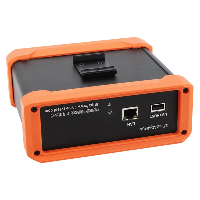
The last application is the quietest and the fastest growing. A battery-powered node bolted to a machine, a bearing housing or a structural member can record force and vibration on a schedule, compute basic indicators locally, and transmit only summaries or alarms. Bandwidth stops being the bottleneck because raw data never leaves the node. This is where edge computing collectors have largely replaced the idea of streaming everything to a central rack.
Modal and impact testing
Strong fit
Civil load testing
Strong fit
Rotating machinery
Strong fit
Long term monitoring
Strong fit
Biomedical measurement
Good fit
Dense lab channel counts
Wired preferred
Qualitative fit assessment based on typical field practice, not on measured comparison data.
Edge Computing Collector for Vibration and Noise TestingReview the edge computing collector for industrial vibration and noise acquisition; related Gigabit network instruments suit different frame, drive arrangement, or automation levels.View Product →
Specifications That Decide a Purchase
Datasheets are not written to help you compare. These are the parameters we suggest you pin down before a quotation is issued, in roughly the order they cause problems later.
- Bandwidth and sample rate. Decide the highest frequency you actually need, then allow headroom for anti-alias filtering. A 1 kHz impact event and a 5 Hz bridge sway need very different hardware.
- Input type per channel. Voltage, IEPE or charge. A node that covers all three on the same chassis is far more useful than one that covers only IEPE.
- Noise floor and resolution in engineering units. Ask for the noise floor in millivolts or in fractions of the rated force, not just the converter bit depth.
- Synchronization method. Hardware trigger, time stamping with clock discipline, or both. Ask what the guaranteed sample alignment across nodes is.
- Channel count per node and per system. Fewer nodes means simpler synchronization and fewer batteries, which usually means a better test.
- Battery life at your duty cycle. Continuous streaming and event-triggered recording are different products. Get the figure for your mode of operation.
- On-board buffering and retransmission. Radio dropouts are normal. Whether the node fills the gap is not.
- Environmental rating and safety. Ingress protection, temperature range, and intrinsic safety certification if the measurement sits in a hazardous area.
- Calibration path. How the sensor is calibrated, how traceability is documented, and whether you can verify the chain on site with a portable calibrator.
Synchronization: The Quiet Challenge
Two wireless nodes will never share a perfect clock. Each runs on its own oscillator, and even a well-behaved crystal drifts by a few parts per million. Over a ten-second record that is invisible. Over a two-hour static load test or a long operational monitoring session, it becomes a systematic time error between channels that no amount of post-processing can guess away.
There are three workable answers. The first is a shared hardware trigger, which only aligns the start instant and leaves drift uncorrected. The second is periodic time synchronization over the radio link, which keeps nodes close enough for typical dynamic analysis. The third is a proper time distribution protocol with timestamped packets at the receiver, which allows drift to be measured and corrected in software. Systems that do the third properly are the ones that let you compare a force channel on node A with an acceleration channel on node G without arguing about phase.
Two related details deserve equal attention. Offset and drift behaviour determines whether a static force reading is meaningful at all, which is why zeroing procedures matter as much as resolution. And packet buffering determines whether a brief radio dropout produces a gap or a repaired record. A chain that handles both gracefully is worth more than one with a slightly higher headline sample rate.
How We Approach Cable-Free Force and Vibration Testing
Our work at Yangzhou Zhenzhong Testing Technology sits at the junction where these questions actually get answered. We build ZT series force and vibration sensors, dynamic signal analyzers, excitation equipment and calibration instruments, and we integrate them into complete testing systems for civil engineering, aerospace, energy, rail and road transport, marine, machine tool and research applications.
The practical advantage of that position is that the wireless question stops being a hardware question and becomes a chain question. A force sensor, its conditioning, the node that digitizes it, the network that carries it and the software that analyzes it are all part of one measurement path, and the error budget has to be managed across the whole path rather than at any single point. That is why we keep the sensor, acquisition and analysis side of the portfolio closely coupled instead of treating them as unrelated catalogue items.
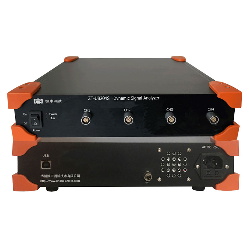
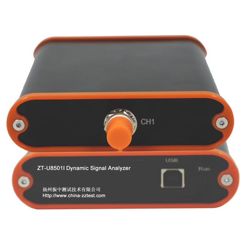
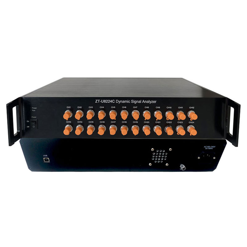
For teams building a distributed measurement, the usual starting point is a force transducer plus a multi-channel acquisition node, or a portable dynamic signal analyzer for smaller campaigns. When the test involves structural excitation, an instrumented modal force hammer with a known sensitivity provides the reference force, and the same record is used for the modal analysis software. When the measurement is expected to run for months rather than hours, the architecture shifts toward edge processing so that only meaningful data travels.
If you want to see how these pieces are combined in practice, the vibration and dynamic testing systems overview walks through the system level view, and this comparison of dynamic signal analyzers explains why the acquisition front end matters as much as the sensor itself.
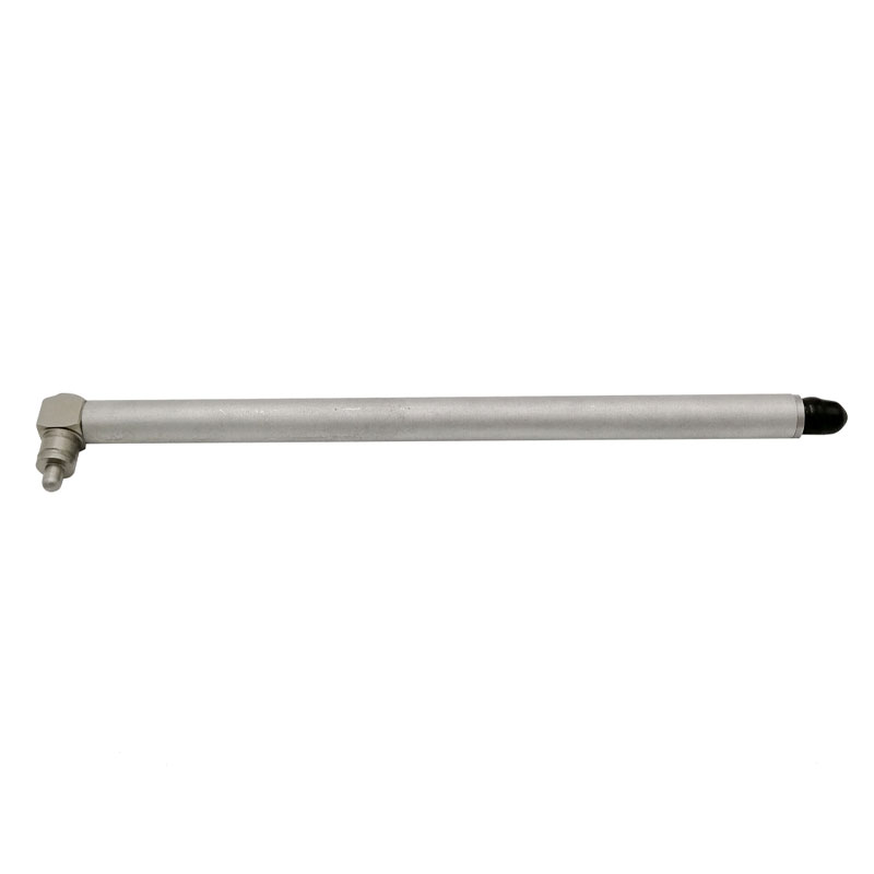
FH Series Modal Force HammersReview FH series modal force hammers with interchangeable buffer heads and counterweights for impact testing, resonance testing, and modal analysis of damped structures.View Product →
A Field Checklist for Trustworthy Numbers
Most disappointing wireless measurements trace back to procedure rather than hardware. This sequence catches the majority of them.
- Define the frequency range of interest before anything else, and confirm that the sample rate and filter settings support it.
- Inspect and mount the sensor properly. A force sensor that is not seated flatly on its mounting surface measures the mounting, not the structure.
- Zero or tare the channel in the actual test configuration, with the fixture in place and the structure in its normal condition.
- Check the offset an hour later. If it has moved appreciably, temperature and drift are part of your measurement whether you like it or not.
- Verify synchronization with a single deliberate tap on the structure that all channels should see, then inspect the arrival times.
- Run a short wired reference channel if any is available. Agreement is the cheapest confidence you will ever buy.
- Record metadata: sensor serial numbers, sensitivities, node identities, sample rates, filter settings and environmental conditions.
- Save a baseline record of the structure in its normal state, so a future measurement has something to be compared against.
Questions We Hear Most
How do I zero a wireless force sensor?
Zeroing removes the static offset that the transducer and its electronics present at the start of a test. Do it with the sensor installed and loaded exactly as it will be during the measurement, allow the electronics to reach thermal equilibrium first, and record the offset value so you can prove later what was subtracted. Then verify after a period of running that the zero has not wandered. On a truly dynamic measurement the zero matters little; on a static or quasi-static one it matters more than almost any other setting.
Can a wireless chain really replace a wired one for modal testing?
For hammer excitation and moderate channel counts, yes, provided sample alignment between nodes is documented and the software treats wireless channels as first-class channels. For high channel counts in a controlled laboratory, a wired rack is usually still simpler, faster to configure and easier to defend in a report.
What battery life should I expect?
There is no universal answer, because the number depends almost entirely on duty cycle and sample rate. A node that wakes for ten seconds every hour can run for months, while the same node streaming continuously at a high sample rate may last a single working day. Always ask for the figure at your operating mode, not the best case in the datasheet.
Wireless force measurement has matured to the point where the interesting engineering has moved away from the radio and back to the measurement itself. The transducer still has to be chosen for the right force range and the right dynamics, the front end still has to be quiet, the clocks still have to agree, and the calibration still has to be traceable. When those fundamentals are handled properly, cutting the cable changes how quickly you can instrument a structure and where you can measure at all, without changing what the data means.
If you are planning a distributed force or vibration measurement and want a second opinion on the architecture before the hardware is ordered, our team is happy to talk through it. You can reach us at sales@china-zztest.com or on +86-0514-85764839, and we will tell you honestly when a cable is still the better answer.

 English




















 Address : No. 85, Hetao West Road, Hanjiang District, Yangzhou City, Jiangsu Province, China
 Phone: +86-0514-85764839
 Tel: +86-0514-85764839
 Email: sales@china-zztest.com
