Cables are the least glamorous part of a vibration test, and far too often they are the part that decides whether the test succeeds. One damaged connector, one ground loop, or one cable that starts generating its own charge as it flexes under a vibrating structure can turn a clean measurement into a week of puzzling. That is the practical reason wireless accelerometers have moved from laboratory curiosity to a standard tool in structural, machinery, and transport testing.
This article looks at what a wireless accelerometer really is, where cable-free measurement genuinely pays off, which specifications decide whether the recorded data will be usable, and how a wireless front end fits into a complete vibration and dynamic testing system. The perspective here comes from people who spend their working days building sensors, acquisition hardware, calibration instruments, and the software that ties them together, so the emphasis is on what survives a field campaign rather than what looks impressive on a specification sheet.
What "Wireless" Really Means in a Vibration Measurement Chain
The word wireless gets used loosely, and that causes a lot of confusion when engineers compare products. In practice, three arrangements dominate the market, and they solve quite different problems.
- Integrated wireless accelerometer. The sensing element, the analog front end, the analog-to-digital converter, the radio, and the battery all sit inside one sealed housing. You mount the housing on the structure, switch it on, and data appears on a receiver or a laptop. This is the simplest option and the one most people picture when they hear the term.
- Wireless transmitter node plus a conventional accelerometer. A standard IEPE or charge accelerometer plugs into a battery-powered node that digitizes the signal and transmits it. The sensor choice stays open, so you can keep the sensitivity, frequency range, and temperature rating you already trust.
- Distributed or edge digitizing over a network link. The conversion happens close to the sensor, and the digitized stream travels over Wi-Fi, Ethernet, or a mobile link instead of an analog cable. This is where wireless thinking overlaps with modern networked and edge acquisition architectures.
In every case the measurement physics is unchanged. A seismic mass moves, a piezoelectric crystal or a micromachined element converts that motion into charge or voltage, and the signal is conditioned and digitized. Wireless changes only two things: how power reaches the measurement point, and how the bits leave it. Keeping that in mind makes product comparisons much clearer, because it separates sensor questions from communication questions.
Why Cable-Free Measurement Is Often Worth the Trade
Anyone who has instrumented a long bridge span, a wind turbine nacelle, or a rotating shaft knows the arithmetic. Cable is cheap per metre, but routing it, protecting it, clamping it, and re-checking it after the third person walks past is not. Cable also behaves like an antenna for noise, and a cable that moves while the structure vibrates can inject triboelectric charge directly into a high-impedance input. Slip rings solve the rotating-shaft problem only partially, and they add wear and maintenance.
Wireless nodes remove that entire layer of risk. They also change the economics of a test: a channel can be added in minutes rather than hours, and a layout can be rearranged after a first look at the data without pulling conduit. The trade is real, though, and it is worth stating plainly before the comparison table.
General comparison of a wired accelerometer channel and a wireless accelerometer node; actual performance depends on the specific hardware and configuration chosen.
| Aspect |
Wired channel |
Wireless node |
| Installation effort |
Higher; routing and protection dominate |
Lower; mount, power on, verify link |
| Cable-related noise |
Present; grounding and shielding matter |
Largely removed |
| Channel count ceiling |
High, limited mainly by hardware and power |
Moderate; radio bandwidth and batteries set limits |
| Phase and time alignment |
Inherently tight on shared clock hardware |
Depends entirely on the synchronization design |
| Power |
Mains or system supply |
Battery or local energy source |
| Best fit |
Dense modal surveys, permanent racks, high-frequency work |
Distributed structures, rotating machinery, temporary campaigns |
Anatomy of a Wireless Node: Four Blocks That Decide Everything
Strip away the enclosure and a wireless node is four functional blocks, each of which can quietly limit your measurement.
Sensing element
Piezoelectric, IEPE, or MEMS. Sensitivity, frequency range, temperature behaviour, and transverse response all come from here, not from the radio.
Signal conditioning and converter
Charge conversion or IEPE constant-current supply, anti-alias filtering, and the analog-to-digital stage. This block sets noise floor and usable dynamic range.
Time base
The internal clock plus whatever synchronization scheme links nodes together. It decides whether data from separate units can be compared in phase.
Radio and power
Transmission rate, duty cycle, buffer memory, and battery capacity together define how long and how densely you can record before returning to the structure.
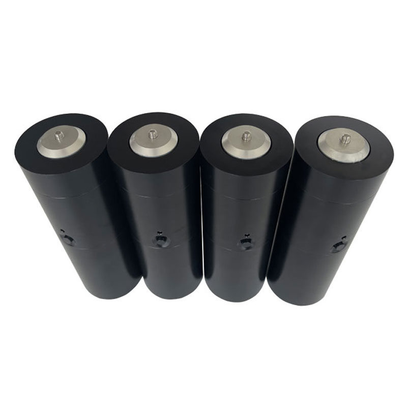
Because the second block is where most practical compatibility questions arise, it is worth knowing that a well-designed node usually accepts a standard  IEPE Accelerometers for Vibration and Dynamic TestingBrowse this IEPE accelerometer category when selecting a sensor family that fits a node's required sensitivity and frequency range.View Product → through a short pigtail, which lets you pair the node with the sensitivity and frequency range the structure actually demands instead of accepting whatever element happens to be soldered inside.
Choosing the Sensor Behind the Radio
Once you accept that the radio is only a transport layer, sensor selection follows the same logic as any wired project, with a few wireless-specific wrinkles.
Sensitivity against range
High sensitivity buys resolution at low amplitude but clips sooner on shock-loaded machinery. For a bridge ambient-vibration survey, a high-sensitivity unit is usually right; for a gearbox with impulsive events, a lower-sensitivity, wider-range unit prevents overload and the distortion that comes with it. Check the specified amplitude range at the frequency you care about, not just the headline number.
Charge, IEPE, or MEMS
Charge accelerometers tolerate high temperatures and offer wide dynamic range, but they need a charge amplifier, which is why they usually appear in nodes with built-in conditioning. IEPE accelerometers are the workhorse for general vibration and modal work, combining a built-in amplifier with simple two-wire connection. MEMS devices are compact, DC-capable, and low in cost, which suits orientation and low-frequency tilt-sensitive measurements, but they are generally noisier at high frequency than a good piezoelectric element.
Mass loading and mounting
A sensor that is heavy relative to the structure becomes part of the structure. On thin panels, small composite components, and lightweight test articles, a miniature triaxial accelerometer is often the only honest choice, because it captures three directions without tripling the mounted mass. Adhesive mounting lowers the usable frequency range compared with a stud, and a magnet lowers it further, so the mounting method belongs in the test plan, not in the field improvisation.
Specifications That Decide Whether the Data Is Usable
Datasheets from different suppliers are rarely organized the same way. The checklist below groups the numbers that actually change the outcome of a test.
Practical specification checklist for evaluating a wireless accelerometer or wireless acquisition node before a measurement campaign.
| Specification |
Why it matters |
What to verify |
| Frequency range |
Defines which structural modes are visible |
Rated range with the chosen sensor and filter |
| Sampling rate |
Sets the anti-alias headroom |
Per-channel rate, not the aggregate stream |
| Resolution and noise floor |
Determines detectable amplitude |
Noise in the band of interest |
| Synchronization |
Controls phase between nodes |
Method, and drift over the recording length |
| Battery and buffering |
Sets campaign duration |
Record time at the rate you will actually use |
| Environmental rating |
Survivability in the real location |
Ingress protection and temperature limits |
| Data path |
Streaming versus on-board recording |
Whether loss of link loses data |
Synchronization, Drift, and Phase: The Quiet Deal-Breaker
If you only need amplitudes at separate points, almost any wireless system will do. The moment you want mode shapes, operating deflection shapes, or phase relationships between two ends of a structure, time alignment becomes the whole game. Two nodes whose clocks disagree by even a small fraction of a period will produce a phase error that grows with frequency, and that error can be mistaken for damping or for a split mode.
Good systems attack this in more than one way. Some distribute a synchronizing reference to every node so that all converters sample on a common time base. Some timestamp samples against a disciplined clock and correct for offset in post-processing. Some rely on a wired trigger or a shared beacon. Whatever the mechanism, ask two questions during selection: how is the clock disciplined, and how much does the alignment drift over a ten-minute or one-hour recording? The answer matters far more than the transmission range quoted on the box.
Where Wireless Accelerometers Earn Their Keep
Wireless is not a universal replacement for a wired rack, and pretending otherwise leads to disappointing projects. It shines in specific situations.
- Civil structures and bridges. Long spans, awkward access, and temporary campaigns where cabling would need road or rail closures. Ambient and forced-vibration surveys for modal identification are a natural fit.
- Rotating machinery and predictive maintenance. Gearboxes, pumps, motors, and shafts where cable routing is impractical and where a node can sit for weeks collecting trend data.
- Rail, road, and transport testing. Onboard measurement on vehicles and track, where weight and cable routing are constant constraints.
- Marine and offshore. Structures where moisture and cable damage are the dominant failure modes.
- Aerospace ground testing. Large test articles with many temporary measurement points that change between build stages.
- Teaching and research laboratories. Fast setup lets a class instrument several configurations within one session.
Long unattended monitoring
Very high channel modal survey
Phase-critical high-frequency work
Illustrative relative fit by scenario. It shows where cable-free measurement usually has the advantage, not measured performance of any specific product.
Installation and Field Craft That Prevents a Retest
Most disappointing wireless datasets trace back to preparation rather than to electronics. The following sequence has saved more campaigns than any single specification.
- Decide the frequency range you must resolve first, then set the sampling rate with comfortable anti-alias margin.
- Choose the mounting method deliberately: stud where the surface allows, adhesive for thin or delicate parts, magnet only for rough trend checks.
- Record orientation and position for every node. Without that, a mode shape is just a set of numbers.
- Check the link budget in the actual environment, not in the car park, and note any structure that blocks the radio path.
- Estimate recording duration from battery capacity at the real duty cycle, then add a margin for the visit you hope not to repeat.
- Run a functional check on the whole chain before the structure is excited. A quick verification against a known reference catches a reversed axis, a dead channel, or a loose mount in two minutes.
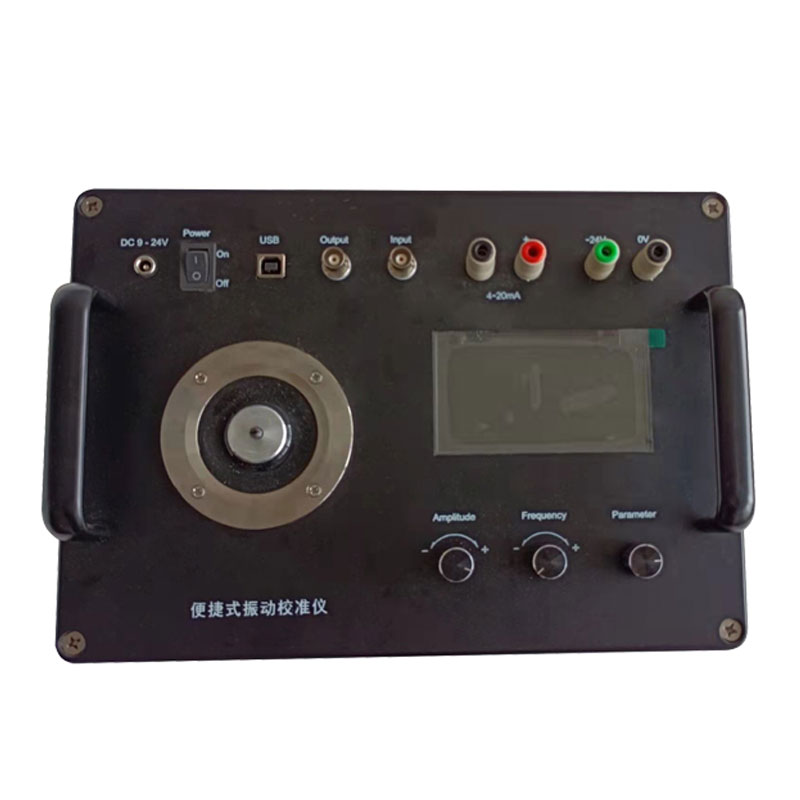
That last step is where a portable reference source earns its place in the case, because it validates the sensor, the node, and the recording settings together rather than one at a time.
Portable Vibration Calibrators and Handheld Shaker CalibratorsReview portable vibration calibrator options for validating sensors, nodes, and recording settings as part of a complete measurement chain.View Product →
From a Wireless Node to a Complete Test System
A node is a component, not a system. Real projects combine sensors, digitizing hardware, a transport layer, analysis software, and a calibration route, and the interfaces between those parts determine how smoothly the work goes. Teams that treat the wireless link as one replaceable block within that chain can move between a battery-powered field node, a networked instrument, and a rack-mounted acquisition chassis without rewriting their test procedure.
That philosophy is visible in how modern networked acquisition hardware is organized. Interface families such as USB, 100 Mbps network, gigabit network, and plug-in gigabit Ethernet chassis cover different channel counts, sampling needs, and installation conditions, while edge computing collectors push digitizing and preprocessing closer to the measurement point. Understanding how these options differ from a conventional analyzer architecture makes procurement decisions much easier, and it helps a test engineer match hardware to the physics rather than to a marketing category.
Edge Computing Collectors for Vibration and Noise Data AcquisitionReview the Edge computing collector category for networked acquisition architectures that digitize and preprocess data closer to the measurement point.View Product →
It is also worth remembering that the acquisition stage is only half of the picture. Modal analysis, order tracking, and fault diagnosis all depend on software that understands the measurement context, and on a calibration chain that keeps the numbers honest. Companies that build the whole chain in-house tend to be good at answering the awkward question: what happens to my data when the radio link degrades? A well-designed test system answers it before the campaign starts, usually with local buffering, a clear status indication, and a documented recovery path.
For readers who want to go deeper into how acquisition front ends differ in architecture rather than in packaging, our note on how a dynamic signal analyzer differs from a traditional instrument is a useful companion to this article, because it explains why channel synchronization is a hardware property and not a software setting.
Calibration and Traceability in a Wireless Workflow
Wireless measurement introduces one extra risk that wired systems rarely face: the electronics travel with the sensor, so a drift in the node's front end shows up as a change in sensitivity that has nothing to do with the structure. The remedy is procedural rather than exotic. Keep an end-to-end check in the loop, verify sensitivity before and after long campaigns, and record temperature exposure, because piezoelectric elements shift with temperature and the effect can look like a real change in response.
A portable vibration calibrator is the practical tool here. It gives you a known reference at a known frequency, applied to the mounted sensor through the entire chain, and it turns an assumption into a measurement. Teams that build this step into their routine usually discover problems while they are still cheap to fix.
Questions We Hear From Engineers New to Wireless
Can wireless accelerometers replace a wired system entirely?
Rarely, and usually that is not the goal. Dense modal surveys with hundreds of channels, permanent monitoring racks, and measurements at very high frequency remain the natural territory of wired acquisition. Wireless adds reach, not raw channel density, and the strongest test setups combine both where each is appropriate.
How long does a battery actually last?
It depends almost entirely on duty cycle, sampling rate, and whether data streams continuously or is buffered on board. The honest calculation starts with the recording schedule you intend to run, not with the standby figure on the datasheet, and it should always include a margin for the second visit you would rather avoid.
Is a wireless measurement less accurate?
Not inherently. The sensing element and the converter set accuracy, and good nodes use the same class of components found in wired instruments. What wireless adds is a synchronization question and an environmental one, and both are solved by design and procedure rather than by accepting a permanent penalty.
Bringing It Together
Wireless accelerometers are best understood as a transport solution wrapped around a measurement that has not changed in decades. Decide what frequencies and amplitudes you must resolve, then pick the sensing element that reaches them, then choose the node whose time base, battery life, and environmental rating match how and where you will actually record. Check the mounting, note the orientation, verify the chain against a reference, and treat the data link as one replaceable part of a larger system rather than as the centerpiece.
Approached that way, cable-free measurement stops being a compromise and becomes a straightforward engineering choice: it removes the failure modes that cables bring, adds reach to structures that were previously awkward or unsafe to instrument, and leaves the physics of vibration measurement exactly where it has always been.

 English




















 Address : No. 85, Hetao West Road, Hanjiang District, Yangzhou City, Jiangsu Province, China
 Phone: +86-0514-85764839
 Tel: +86-0514-85764839
 Email: sales@china-zztest.com
