A structural modal test is running behind schedule. The engineer taps the test object with an instrumented hammer, watches the response decay in about three hundred milliseconds, and sees only a handful of samples on the screen. The damping estimate looks like a guess, the frequency response function carries an alias, and the run has to be repeated. This is exactly the situation where high-speed data acquisition stops being a brochure term and becomes the difference between usable data and a wasted afternoon.
In the context of vibration and dynamic testing, high speed is not one specification. It is a combination of sampling rate, converter resolution, and channel-to-channel timing that determines whether a physical event is captured faithfully. This article explains what those numbers mean in practice and how to match them to the demands of modal analysis, impact tests, and machinery diagnostics.
What "High Speed" Actually Means in a Dynamic Signal Analyzer
The first point to settle is that there is no universal speed threshold that marks a system as high speed. The right sample rate is the one that preserves the highest frequency you intend to analyze, plus a filter margin. Dynamic signal analyzers conventionally sample at 2.56 times the upper frequency limit of the analysis band. If a modal test covers 0 to 2 kHz, a 5.12 kS/s rate is enough in theory; a rotating-machinery fault survey up to 30 kHz calls for roughly 77 kS/s; a short acoustic or mechanical transient can justify 256 kHz or more.
High speed is therefore relative to the measurement. For a bridge test resolving modes below 100 Hz, 256 kS/s is overkill. For a component that receives a millisecond-scale impact, the same rate may be exactly what catches the true peak. The reliable procedure is to compute the rate from the physics of the test, not to pick the largest number in the catalog.
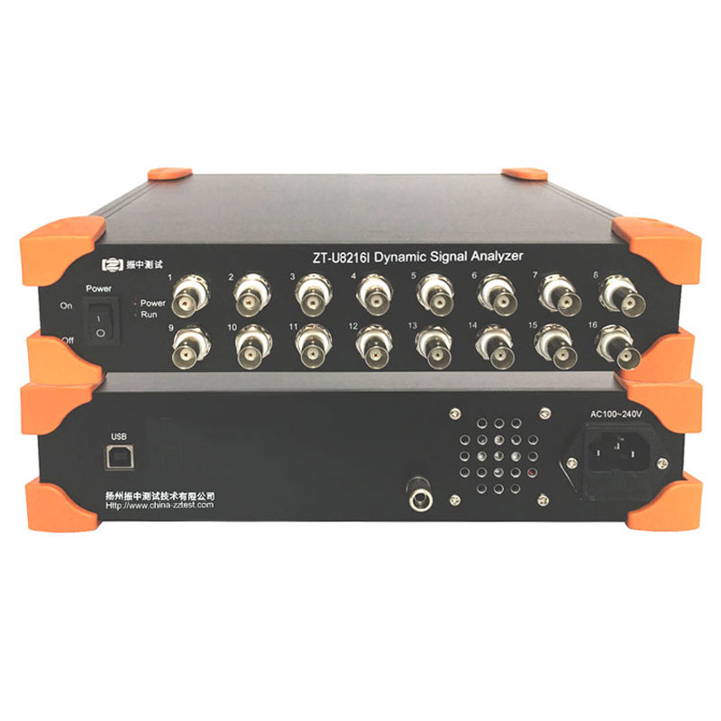
When the test genuinely demands extreme speed, the hardware has to follow. At the upper end of compact front-ends, the ZTU8508C dynamic signal analyzer reaches 1 MHz sampling, a capability aimed at very short transients, high-frequency acoustic events, and similar single-channel applications.
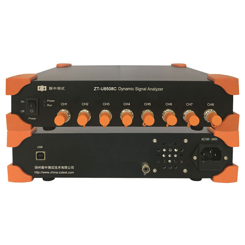 ZT-U8508C 1 MHz Sampling Dynamic Signal Analyzer for Transient CaptureThis eight-channel analyzer delivers 1 MHz per-channel sampling with synchronized clocks, making it suitable for capturing very short transients and high-frequency acoustic events in single-channel or multichannel modal analysis.View Product →
Sample-rate capability also depends on the link between the front-end and the host computer. The selection of interface families in current dynamic signal analyzers illustrates the typical trade-offs:
Interface families and what they imply for high-speed vibration and noise acquisition.
| Interface |
Example catalog models |
Channel range |
Sample-rate highlights |
| USB 2.0 |
ZTU8201C, ZTU8301C, ZTU8232C, ZTU8508C |
1 to 32 |
256 kHz single-channel; 128 kHz multichannel; 1 MHz top rate |
| 100 Mbps network |
ZTN8116C, ZTN8201I, ZTN8204I, ZTN8208I |
1 to 16 |
24-bit portable designs with voltage or IEPE input |
| Gigabit network |
ZTG8204C, ZTG8304C, ZTG8604C |
4 |
Four-channel analyzers for remote or continuous setups |
| Plug-in gigabit |
ZTG9232I |
32 |
Dense channel expansion for larger arrays |
The bus architecture changes the system layout as much as the data rate. Network-based front-ends can sit close to the sensors and stream data over long cable runs, while USB front-ends behave naturally as bench instruments. For a high-channel-count modal test or a permanent monitoring installation, physical placement is often the deciding factor even when the sample rate alone would not be.
Where Sampling Rate Decides the Outcome
Tests that punish an insufficient sample rate share a common shape: they are short in time and broad in spectrum. Continuous low-frequency vibration tolerates modest rates; hammer impacts, crack-related transients, and high-frequency bearing events do not.
In modal testing, the requirement is usually moderate but unforgiving. Use 2.56 times the highest mode frequency you want to identify. Sampling too low produces aliased peaks that look exactly like real modes; the error is silent because the analyzer cannot represent frequencies it never measured. The classic symptom is a frequency response function whose resonance peaks move or change amplitude as you change the analysis band.
In impact and transient testing, a higher rate buys two separate advantages. First, the peak amplitude of a hammer pulse or shock event is more likely to be captured; a one-sample peak measured at a low rate can be underestimated by tens of percent. Second, a short burst window retains the waveform shape needed for a clean Fourier transform.
In machinery diagnostics, early bearing faults generate repetitive shock pulses that excite resonances far above the shaft rotation frequency. A defect frequency at 150 Hz can remain invisible if its ringing extends to 20 kHz while the analyzer samples at 10 kS/s. Practical diagnostic measurements on such machines require per-channel rates of 50 kS/s or more, which is where a dedicated high-speed front-end earns its place.
For transient measurements of this kind, one fast channel is often worth more than a slow array. The ZTU8301C single-channel dynamic signal analyzer with 256 kHz sampling is a representative example of this approach.
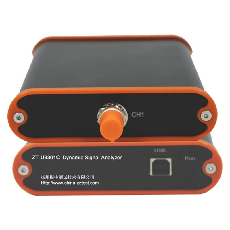 ZT-U8301C 256 kHz Single-Channel Dynamic Signal AnalyzerWith 256 kHz sampling and a 100 kHz analog bandwidth, this compact unit offers oversampling for anti-aliasing and a charge input range up to ±10000 pC for piezoelectric sensors.View Product →
The fastest setting is not always the best setting. Doubling the sample rate doubles the file size and the processing load while adding almost no information when the physical signal is band-limited. Match the rate to the spectrum, not to the catalog.
Specifications That Matter as Much as Sample Rate
A specification sheet full of sampling numbers can hide the four parameters that govern measurement quality: per-channel rate, converter resolution, input type, and inter-channel synchronization.
- Per-channel rate versus aggregate throughput. A system may advertise a high total throughput, but when that figure is divided across 32 channels, the per-channel rate can fall below the requirement of your test. Always confirm the rate at the full channel count you plan to use.
- Converter resolution. Vibration signals often combine a large low-frequency component with a very small high-frequency one. A 24-bit converter provides enough dynamic range to resolve both in a single record; a 16-bit converter may bury the small component in quantization noise. Most dedicated analyzers in the catalog are 24-bit for exactly this reason.
- Input type and signal conditioning. Accelerometer-based tests need IEPE constant-current excitation, charge-output accelerometers need a charge amplifier, and general-purpose measurements need plain voltage input. An analyzer that supports voltage, IEPE, and charge input simplifies reconfiguration across different test campaigns.
- Synchronization. Modal and operational deflection shape tests depend on phase relationships between channels. Simultaneous sampling on every channel preserves those relationships; sequential multiplexed sampling corrupts them. For a large structural test, synchronization matters more than an extra megahertz on the spec sheet.
When a modal survey needs dozens of synchronized responses, the practical bottlenecks are channel count and time alignment, not single-channel speed. The ZTU8232C 32-channel dynamic signal analyzer samples at 128 kHz over a USB 2.0 connection, which shows how multichannel capacity and realistic speed are combined in one unit.
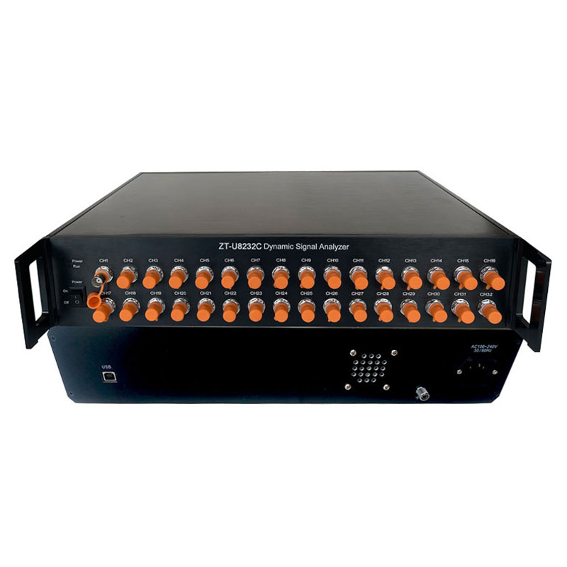 ZT-U8232C 128 kHz 32-Channel Dynamic Signal AnalyzerFeaturing 32 synchronized acquisition channels with dedicated A/D converters and tracking anti-alias filters, this analyzer supports high-channel-count modal testing over USB 2.0 while maintaining time alignment.View Product →
Five Checks Before You Choose a High-Speed DAQ
- Define the highest frequency you must resolve, then multiply it by 2.56. That number, not the brochure headline, is your minimum sample rate.
- Verify the sample rate at your planned channel count, not at one channel. Ask specifically what happens to throughput when every channel is enabled.
- Match the input modes to your sensors: voltage, IEPE, or charge. Confirm that the analyzer supplies sensor excitation and that its input ranges suit your signal levels.
- Check trigger and timing behavior for transient work. Pre-trigger capture, burst mode, and reliable timestamps matter more than an extra digit on the sample rate.
- Consider the total measurement chain, not just the front-end. The value of a supplier who delivers sensors, acquisition hardware, and software together can outweigh the savings of integrating components from several vendors yourself.
For engineers assembling a complete measurement chain, a turnkey testing solution keeps the whole signal path under one specification and removes most integration risk. Those who are still deciding between a general-purpose acquisition board and an analyzer purpose-built for vibration will find the practical differences outlined in an earlier article on how a dynamic signal analyzer differs from a traditional data acquisition system.
The Practical Bottom Line
High-speed data acquisition is not an arms race for the largest possible sample rate. It is an exercise in matching bandwidth to physics. Define the highest frequency in your measurement, apply the 2.56 margin, verify that the chosen instrument delivers that rate on every channel you intend to use, and confirm that the input stages match your sensors. If those conditions hold, the recording will represent reality. If they do not, no software upgrade will fix it.
Buying a fast system is easy. Buying a system whose speed, resolution, channel count, and synchronization are engineered around a real test is what separates a reliable measurement campaign from a long debugging session. Start with the physics, then read the specification sheet.

 English




















 Address : No. 85, Hetao West Road, Hanjiang District, Yangzhou City, Jiangsu Province, China
 Phone: +86-0514-85764839
 Tel: +86-0514-85764839
 Email: sales@china-zztest.com
